

|
|
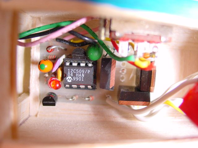
This ESC is based on Mike Norton's design. I have modified the PCB to accept two FETs, which increases current capacity to more than 20 Amps. |
|
|
The circuit is quite simple, as all the hard work is done inside a PIC microcontroller. Brake and BEC (Battery Eliminator Circuit) are optional. Cutoff voltage is set by choosing the value of resistor R7. The Schottky diode (1N5821 or equivalent) is now mounted directly on the PCB, instead of on the motor. |
|
|
My PCB layout prints actual size at 600dpi, or double-size at 300dpi. To get the image, click on the small preview to the left, then Right-click on the full-size image and choose "save picture as..". If you can't get it to print the correct size, download this zip file which contains 300dpi and 600dpi BitMap versions. These should print actual size using Kodak Imaging for Windows. |
|
Added 25th Nov, 2003. Due to popular demand, a colourful overlay diagram showing component placement and wiring! |
Value of R7 for Different Cutoff Voltages
| Cells | Nom. Volts | Cutoff Volts | R7 |
| 5 | 6V | 4.5V | 760 Ohms |
| 6 | 7.2V | 5.4V | 390 Ohms |
| 7 | 8.4V | 6.3V | wire link |
Modifications for 4.8V operation (4 cells and no BEC)
Update: 23rd August, 2001
I have modified the firmware to improve glitch handling. I also replaced the Brake indicator LED with an audible arming indicator. The new source codes are spd400.asm and spd400.inc . The new hex file is SPD400.HEX .
 The graph at right shows throttle response (click on it to see a more detailed
plot). Note how the PWM ratio (colored black) is curved. This seems to
concentrate most of the control at the lower end, but power is proportional to
PWM squared, so the motor's response (purple) is linear. Throttle control
is more natural using this reverse-exponential compensation. You can see that
center stick (1.5mS) produces 50% power, wheras a non-compensated throttle would
only produce 25% at this setting. The flat areas at 0% and 100% power are quite
large, to ensure that full throttle range is available on transmitters that
cannot generate the whole 1mS to 2mS servo pulse range. Notice the 'step'
effect in the graph lines. This is due to the limited number of PWM ratios that
can be generated (there are 40 steps).
The graph at right shows throttle response (click on it to see a more detailed
plot). Note how the PWM ratio (colored black) is curved. This seems to
concentrate most of the control at the lower end, but power is proportional to
PWM squared, so the motor's response (purple) is linear. Throttle control
is more natural using this reverse-exponential compensation. You can see that
center stick (1.5mS) produces 50% power, wheras a non-compensated throttle would
only produce 25% at this setting. The flat areas at 0% and 100% power are quite
large, to ensure that full throttle range is available on transmitters that
cannot generate the whole 1mS to 2mS servo pulse range. Notice the 'step'
effect in the graph lines. This is due to the limited number of PWM ratios that
can be generated (there are 40 steps).
Parts Substitutions added 14th April 2004
Q1 can be replaced with any enhancement mode PMOSFET which can handle at least 20V and has RDSon of 0.1 Ohms or lower, eg. 2SJ255. Q2 and Q3 are NMOSFETs with logic level gate drive (must turn on with 4.5V or less), VDss = 30V or better, and RDSon lower than 0.01 Ohms. I have used the HUF76143. Other good choices are the IRL3803 or SUP75N03-04. You could use two cheap FETs in parallel to get a low enough RDSon, eg. 2 x IRL3103 = 0.008 Ohms.
Schottky diode D1 should be rated at least 3A and 20V. Q4 can be replaced with a 2N7000 or equivalent. Q5 can be just about any PNP low power transistor, eg. BC327, 2N3906. IC2 must be a low dropout voltage 5V regulator, if you want to use a 6 or 7 cell battery (the standard 7805 regulator has a dropout voltage of 7V, so needs 8 cells or more). I use the ROHM BA05T. Check the pinouts, some regulators have input and output pins reversed!
If you want to modify the source code, a Flash PIC will save lots of money (the 12C509 can only be programmed once unless you get the expensive windowed verison). The 12F629 and 12F675 are pin compatible, and just need slightly modified coding (spd475.zip).