The Flash4 transmitter generates channel 5 (usually used for retracts), but has no means to control it. To make the Retract channel functional you just need to remove a link from the PCB, add a capacitor, and wire in a resistor and switch.
How it Works
Channel 5's control input is a variable voltage just like the other channels, but this is encoded into only two positions, 'gear up' and 'gear down'. The changeover occurs when input voltage goes above or below a threshold of 2.0V. When the Retract Switch is closed, input voltage to the encoder is about 3V, when opened the voltage is 0V (R1 sets the higher voltage point). C1 bypasses any stray RF energy that might be picked up by the switch wiring (which otherwise could cause the encoder to misoperate).
Installing the Retract Switch
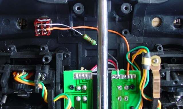
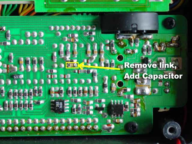
Unsolder the link from the main circuit board, and add the 1nF capacitor in its place. Drill a hole and mount the switch on the front panel. Connect a 4K7 resistor between the upper switch contact and the 2nd terminal on the left-hand trim board. Finally, connect a wire from the center switch contact to the 5th terminal on the trim board.
|
|
|
|
|